
On Monday we implemented the motor into the middle piece of the plane. We felt this method of squishing the foam between two plates would be a sturdy way of binding the motor to foam. I designed and laser cut a piece of wood to match the carbon fiber mount that already came with the motor and then bolted the two together as well as applying plenty of glue. On top of the motor mount, we built the tail today. We decided to repurpose the foam tail from a plane that had been recently discarded. We also choose to add the servos on the tail this time instead of having the push rods go to servos all the way inside of the fuselage. We then strung the wires from the servos inside of a carbon fiber hexagon that acted as the rear fuselage.
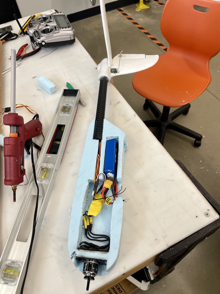
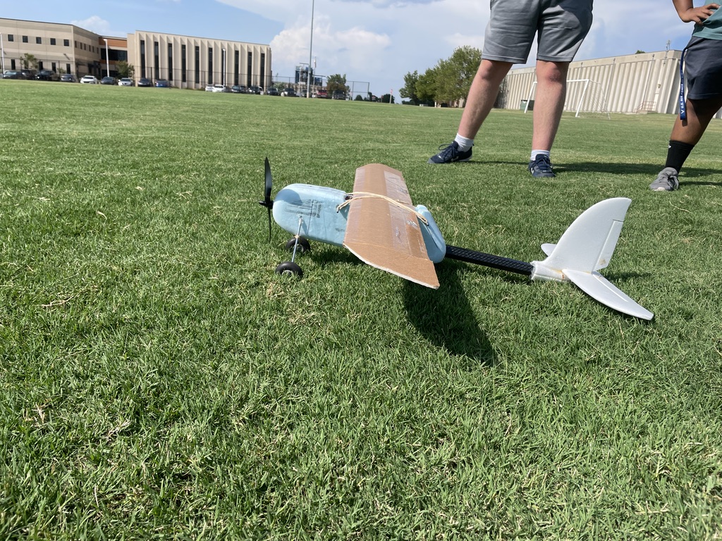
On Tuesday we fixed everything else on the plane including landing gear and then implemented the electronics to the fuselage. Two layers of the foam were glued together and the carbon fiber tail was fastened to that. We decided to repurpose the wing from the previous foam board plane which happened to be a poor idea. After everything was ready we waited on the flight simulator until we were able to go fly. When we were able to fly we first tried taking off from the ground. This didn’t quite work because we didn’t have a rear wheel and the plane started to skew to the right. So we tried throwing it similar to the strategy of the previous plane. The plane glided for about 20 yards but then touched the ground, unfortunately snapping the prop and ripping the motor out from the foam. The landing gear had also dug into the foam and twisted which is why the prop hit the ground. Looking back the plane most likely didn’t fly because it was too heavy compared to the airfoil thickness. The airfoil we were flying was almost flat however we thought that overpowering the motor would overcome this. Today we also ran Into Dr. Jacob and he gave a new mission for our aircraft. The new goal was to eventually implement an inflatable wing, serving as a concept for future deployment of inflatable wings on mars and other missions with the idea that it would take up less space in the capsule it was sent in.
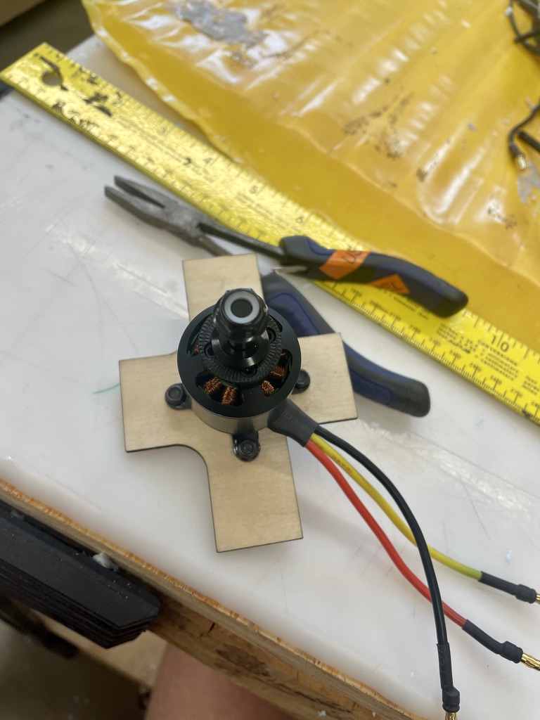
The next day we started to fix the parts we had destroyed the previous day. We changed to a larger motor and a higher voltage battery as well as choosing a battery with less milliAmp hours The new battery was better for higher speeds and larger motors and props as well as by cutting milliAmps we reduced overall battery size and weight however loosing lastingness of the battery which was a good trade off for our purpose. I designed a new motor mount that would attach itself to more of the foam, meaning it would basically have to rip out the entire nose for it to come out. I also designed new landing gear pads that would be 3D printed and create a rigid surface between the metal rods and the foam, ultimately expanding the surface area and decreasing the pressure on a small part of the foam where it would dig in. We also designed a new wing that would replicate the wingspan and chord length (width of the wing) of the inflatable wing. We couldn’t implement the inflatable wing itself because we couldn’t find the plug to inflate it. Also with an inflatable wing the control surfaces are limited. We would most likely need to try and do wing warping which is a pretty hard thing to get right and will be a thing for another day once we get the aircraft flyable.
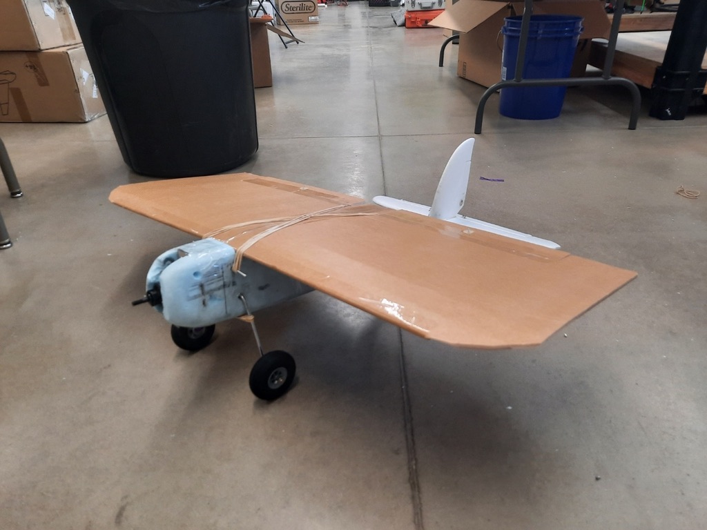
On Thursday we rebuilt the pane with the new wing, landing gear and motor. We also built a rear wheel in hopes it could take off from the ground. However, we had an issue; the new wing had a horrible aspect ratio with about no airfoil once again and it looked extremely awkward on the plane (a great test to see if your ratios are correct). We decided to go ahead and try it anyway with the assumption that it wouldn’t fly. We were correct. However, we obtained good information from this model as we learned we need to be more precise with our ratios when modeling our plane. Also our new motor mount and landing gear was successful and we were almost able to take off from the ground. Also very fortunately we ran into Dr. Jacob again today and we were able to ask a ton of questions about the wing and find the plug to blow it up.
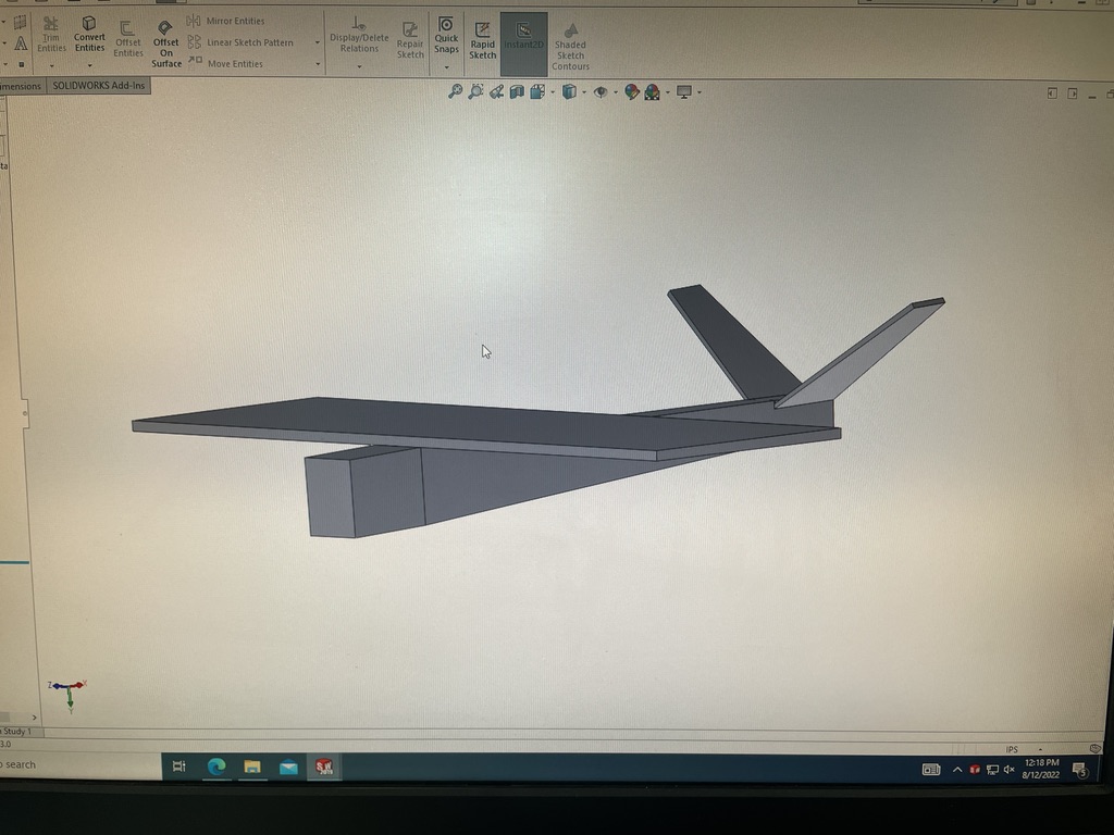
Friday was a really good day as after a night of studying plane modeling and learning the correct theoretical dimensions to fly our predetermined wing (the inflatable wing), I was able to spend the morning designing and modeling the plane on Solid Works. This was a challenge to me as converting from a standard tail to a v tail proved difficult mathematically as well as being a challenge for me on Solid Works. I had originally planned to build the plane with a standard tail, but as we are going to originate by flying tail controls only, a v tail will provide more roll ability. Without ailerons on the wings we struggle to tilt the plane so by adding ruddervons and programming the plane to fly as if the ruddervons are elevons, we will have roll and pitch abilities instead of pitch and yaw. Programming brings us to the next fun part of the day. After talking to some experts in the lab we got the idea that our plane would be extremely hard to fly manually. So to fix this we plan on incorporating a gyroscopic stabilizer board. The system is also fitted with a compass and GPS meaning we could preset a flight plan and it would fly completely autonomously. What we will use it for however is just to stabilize the plane when no controls are being used as well as preventing severe overcorrections and dives. We also programmed it to easily switch from this semi autonomous mode and fully manual. Unfortunately Friday was Micah’s last day and I will be on my own the following week; however very fortunate for me, Micah was able to set most of the gyro stabilizer up by himself while I was working on the complete plane design on Solid Works. After helping with the gyro stabilizer I was able to design the laser cut layout to build the foamboard fuselage and wings. This was a mind twister as I was trying to lay out a pattern of cuts on a sheet to fold it into parts that would create the fuselage. The hard part was that our fuselage cannot all be cut from one sheet of foam board so I needed to find a way to fasten parts together. I also needed to find a way to attach the motor and I designed a mount that will be 3D printed.
There are no comments published yet.